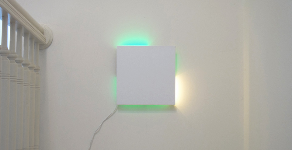
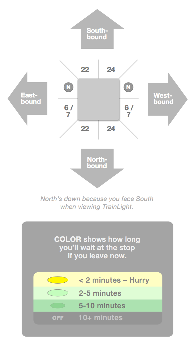
TrainLight hangs on the wall and tells you at a glance which nearby transit lines will get you to your destination fastest. Full explanation here.
How to build a TrainLight:
1. Before You Begin
Make sure you have what TrainLight needs to work:
Transit data: Obviously you need to live near train or bus stops for this to work. Your town also needs to provide arrival and departure information that TrainLight can read. If you happen to live in San Francisco, you’re set. If you’re outside SF, check to see if your local transit system is one of the dozens served by the NextBus transit info system. If it’s not, search Google to determine whether your local transit agency provides a a public XML feed for developers that’s accessible by RESTful calls. If so, you should be good to go. (Let me know if you get it working outside SF – I’ll build a list of confirmed cities.)
Server: You need access to a server that can run the parser. TrainLight’s tiny (less than 5k) and it doesn’t use much bandwidth. But it runs all day, grabbing and sending transit updates every 30 seconds, so make sure your service provider permits that. At first I ran it on my web hosting account at DreamHost, but their policy prohibits any new process that runs repeatedly. So DreamHost kept stopping my TrainLight parser. A friend let me move it to his server, and now it works fine. Make sure that your server, or your hosting service’s server, can run Ruby code, and will let you run a cron job (a scheduling script that will fire off your parser repeatedly when you’re logged out).
Wifi and a power outlet.
2. Ingredients
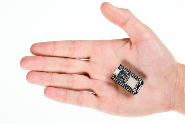
- 1 Photon – $19 from Particle, or 1 Core – $40 from Particle. This is the brain – the microcontroller. I built my TrainLight using the Core before its makers released the Photon, its tinier, cheaper successor. Now I recommend a Photon. It’s smaller, so its one disadvantage over the Core is that soldering will be a little more difficult. But you can skip the microcontroller soldering altogether and just use a breadboard – the $29 Photon Kit includes a breadboard, together they’re small enough to easily fit inside TrainLight frame. (You’ll still need to solder 3 jumper wires to the LED strip, though.)
- A micro USB cable. You can find them for $5 on Amazon, or one comes as part of the $29 Photon Kit.
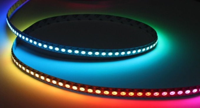
- 1 meter of fully-addressable WS2812B LED strip. I used 60-LED-per-meter weatherproofed Neopixel strip ($25 from Adafruit). You can spend less if you go generic from Aliexpress, especially if you buy the kind without weatherproof sheathing, and especially if you get at least 4 meters’ worth (use the rest for other projects). Avoid the 32 LED/meter strips – anything lower than 60/meter looks jagged and shabby.
- 1 white canvas panel, 12″x12″. About $3 from your local arts/craft store, or online here.
- 1 piece of styrofoam core, 1″ x 10″ x 10″, about $3 from an arts/craft store. Cut in the shape above – remove a section from the center for the microcontroller, plus a diagonal slot for the power cable and light strip. (The precise size and shape of the inner empty section really doesn’t matter, because it won’t be visible. Just make it big enough to comfortably fit your microcontroller, and your breadboard if you’ve got one. A 4″ x 3″ space will be more than enough). Important: Have the store cut it with a hot-wire cutter if you can. Styrofoam’s a pain to cut; it’s hard to make clean cuts. You’ll end up with ragged edges that drop foam crumbs everywhere, and it takes too long. If you can’t get the store to cut it for you, here’s how to cut it yourself. (I know, this is an instruction step in the ingredient list. But it’s so much easier to have it cut at the store that it’s worth mentioning here.)
- 1 switching power adapter, 5V 2A. About $10 on eBay, or you might already have one sitting around the house. Use one that ends in a standard 2.1mm DC plug.
- 1 x 2.1mm female-to-screw-terminal adapter. $5 for 10 on Amazon, or you can probably find them much cheaper at Fry’s or a similar electronics store.
- 1 x 3V-5V Quad-Level Shifter 74AHCT125 – $1.50 from Adafruit.
- 1 Capacitor – 1000uf. About $1.50 at Fry’s, Radio Shack, etc. Or $4.11 for 5 on Amazon. This protects the light strip from voltage spikes that might otherwise burn out the LEDs.
- 1 Resistor – 330 Ohm, 1/2 Watt – Less than $1 online. This is another safeguard against LED damage.
- Wire – 22 gauge if you want to solder, or just jumper wires if you’re using the breadboard that comes with the Spark Core.
- 22 gauge wire – A few feet. That’s maybe $1 worth, depending on how much you buy. It’s cheaper in larger quantities. I have a big $22 spool to use for many projects, but that’s about 100 times what you need for this project.
- Jumper wires – Maybe $2 worth, again depending on how much you buy. Here are some on Amazon.
- Solder. It’s cheap. Maybe $1 worth. The smallest roll is more than you need for this project.
- Spray adhesive, or some other means of sticking the canvas panel to the foam. $6 per can on Amazon for adhesive that works perfectly for this task.
- A few other supplies that you probably already have around the house:
- Transparent packing tape. (Not Scotch tape, that’s too thin and fragile.)
- Duct tape, preferably white
- Framer’s wire, or similar – to hang TrainLight from nails on the wall
- A couple of small nails
- A ruler, or some similar flat, firm, light, long object you can use to attach the framer’s wire. (The wire will slice right through the foam if you attach it directly.)
- Thick card-stock paper or thin cardboard, maybe 8″x10″ worth, that you’ll cut into strips. (Or just stick duct tape to printer paper to make it thick and sturdy.)
- Tools: Soldering iron, short-nose/needlenose pliers, wire cutter/stripper.
- Optional but nice to have:
- 1 pair of 3-pin JST Female to Male Connectors. About $1 on eBay. If you ever want to disconnect your microcontroller from your LED strip, to swap out either piece, this will let you snap them apart and back together easily.
- Painter’s tape – secures and protects the electronics, easily removable.


3. Hardware: Connect The Pieces
Connect the electronics like so:
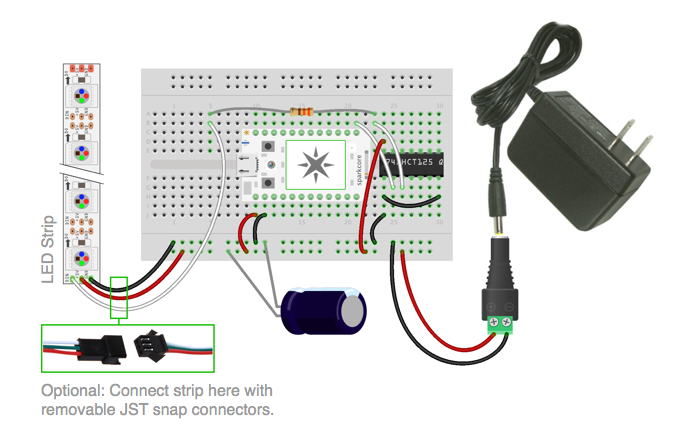
Be sure to use the correct end of the LED strip. The arrows printed on the strip should point away from the end you solder to. Put about 6 inches of space between the LED strip and the microcontroller so they’ll fit easily into the TrainLight frame.
If you want to set this up using a breadboard and you’re new to this, see How to Use a Breadboard. To learn how to solder, see Adafruit’s Guide to Excellent Soldering.
Optional: If you want more detail about this circuit, here’s a link to the circuit diagram in Fritzing format. View it with the free Fritzing app.
4. Hardware: Verify That It Works
Create a free account at Particle’s Build site and register your Particle Photon or Core there.
Follow the getting-started tutorial there to connect your microcontroller to your local wi-fi, and to blink the LED on your microcontroller. Now you know that your microcontroller’s connected and working right.
Then check out the Particle Core/Photon Neopixel library. For future reference: You can always find it via the “libraries” link (the bookmark icon near the lower left of the screen) in your workspace at http://build.particle.io.
Open the “extra-examples.cpp” file there and use that as a starting point to create your own sample app to test the LED strip. In the sample app, change the following 3 variables to:
#define PIXEL_PIN D0
#define PIXEL_COUNT 60
#define PIXEL_TYPE WS2812B
Then flash your microcontroller’s firmware with that code base and run it, the same way Particle’s tutorial taught you to flash and run the intro code.
If you see a rainbow animate along your LED strip, and all the LEDs light up, you’re in business. You’re hardware’s good to go! (If not, you may have a defective light strip, or something else went wrong. Double check all your connections and try again. If it’s still not working, visit http://support.particle.io/ to solve the problem).
Next we’ll replace that animated-rainbow code with the TrainLight code.
5. Software: Flash the Firmware
When you flash firmware, you replace software on a device with new software.
Download (or sync via Github) the following directory “trainlight,” and all the files it contains, to your computer.
https://github.com/seanjsavage/TrainLight/tree/master/firmware/trainlight
Now, flash your microcontroller’s firmware with that code. Particle provides several ways to do this. I recommend using the CLI (command line interface) as described here.
Shortcut: I use this single line each time I want to compile the code on my machine and flash my microcontroller:
cd /[local-path-on-my-laptop]/TrainLight; rm firmware*.bin; spark compile trainlight; spark flash [my-microcontroller-name] firmware*.bin;Your microcontroller’s ready to light your LED strip according to the signals that we’ll send it from the parser, which will run on your server.
6. Software: Run the Parser and Verify That Everything Works
The parser code will live on your server, and every 30 seconds it’ll grab the arrival time predictions for the stops you’re interested in, and send that information to your microcontroller.
Later we’ll customize the code for your city and stops. First, let’s make sure everything works using the default version of the parser code, which works with my 8 stops in San Francisco.
Download (or sync via Github) the following directory “trainlightparser-rb,” and all the files it contains, and place them on your server.
https://github.com/seanjsavage/TrainLight/tree/master/server-side/trainlightparser-rb
If your local transit system publishes feeds via NextBus, download the restbus server and install and run it it on your server as explained in its documentation. (Restbus is a RESTful API for the NextBus XML transit feeds.)
Now you need to set up a cron job – a scheduled process that will repeatedly run the parser code you just uploaded. In the line below, replace [path-to-your-parser] with – you guessed it – the path on your server where you placed the parser. Then replace [your-access-token] with the access token you created when you set up your microcontroller (Step 4). You can find your access token on the Settings page (click the gear icon in the lower left) at http://build.particle.io.
* * * * * cd /[path-to-your-parser]/trainlightparser-rb && SPARK_ACCESS_TOKEN=[your-access-token] /usr/local/bin/ruby trainlight_parser.rb -qNow, add that line to your crontab. Don’t know how? Ask your system administrator, or see CronHowTo.
Next, plug it your microcontroller. If all is well, it will “listen” for the signals that the parser sends it, and it will light up your LEDs accordingly, updating them every 30 seconds. Your light strip should display 8 color “zones” of 7-8 LEDs each, each settling upon either no color (all LEDs off), dim green, bright green or bright yellow, and some of those colors should change every 30 seconds. If that’s happening, you’re in business! Move on to the next step to calibrate those lights to work for YOUR place, and for the transit lines you want.
If it’s not working, you’ll need to troubleshoot.
7. Software: Customize It
It’s time to tailor TrainLight to your place. You’ll need to specify which bus/train lines and stops you want TrainLight to tell you about – there are 8 “zones” or signal areas on TrainLight, so you can select 8 stops like I did, or double it up and just show 4 stops (1 for each side of the square), or whatever you’d like.
Optional: To help you figure this out, and to help remember which stop you assign to each zone, you can download my TrainLight legend diagram and fill it out with your nearby transit lines/stops. It’s in .sketch format – use Sketch 3 (free trial download here) to open and edit the diagram. Decide where you’ll hang TrainLight, then change the arrow directions (northbound, southbound, etc.) to suit the direction you’ll face when looking at your TrainLight.
Open that “trainlight_parser.rb” file and swap out the 8 transit feed URLs in lines 25-47 (below) with the transit feed URLs for the stops and lines that you want to monitor. To find your feed URLs, consult your transit agency’s feed documentation.
For each zone you can specify a single transit line, or you can monitor all the buses/trains going in the same direction at a stop. For instance, below TrainLight’s lighting up zone RB (right bottom) to tell me when the next 6 bus or 7 bus is coming – I don’t care which, because they both go where I want. But in zone RT (right top) it’s only monitoring the N – I don’t want to know about other trains at that stop.
The 8 zones are laid out clockwise starting with the top left. The “id” specifies the zone’s position; TL = top left, RB = right bottom, etc.
      # 22 Southbound
      {:id =>"TL", :url =>"http://skeduapp.com:3000/agencies/sf-muni/routes/22/stops/4005/predictions", :time_interval => 7},

      # 24 Southbound
      {:id =>"TR", :url =>"http://skeduapp.com:3000/agencies/sf-muni/routes/24/stops/4330/predictions", :time_interval => 2},

      # N Westbound
      {:id =>"RT", :url =>"http://skeduapp.com:3000/agencies/sf-muni/routes/N/stops/7252/predictions", :time_interval => 5},

      # 6/71 Westbound
      {:id =>"RB", :url =>"http://skeduapp.com:3000/agencies/sf-muni/stops/14950/predictions", :time_interval => 7},

      # 24 Northbounnd
      {:id =>"BR", :url =>"http://skeduapp.com:3000/agencies/sf-muni/routes/24/stops/4331/predictions", :time_interval => 2},

      # 22 Northbound
      {:id =>"BL", :url =>"http://skeduapp.com:3000/agencies/sf-muni/routes/22/stops/4006/predictions", :time_interval => 8},

      # 6/71 Eastbound
      {:id =>"LB", :url =>"http://skeduapp.com:3000/agencies/sf-muni/stops/14951/predictions", :time_interval => 6},

      # N Eastbound
      {:id =>"LT", :url =>"http://skeduapp.com:3000/agencies/sf-muni/routes/N/stops/7318/predictions", :time_interval => 4}
You want to delay the arrival times to compensate for how long it takes you to walk to the stops. So figure that out – you can start out using Google Maps walking directions to guesstimate. For me that turned out to be not as accurate as timing my walk next time I walked to each stop. (Especially if you have stairs or anything like that, which Google doesn’t take into account). Round each delay time up to the next minute.
Now go back to those same lines 25-47 and change the number following “time_interval =>” for each stop to your delay for that stop.
Now upload that new version of trainlight_parser.rb to your server. If all goes well, your LED strip should start showing predictions for the stops you specified. Double-check by loading a few of those transit feed URLs in a browser, and hitting “reload” while you take a snapshot of Trainlight. The color of the LEDs you’ve assigned to stop should match the prediction times appearing in the transit feed, as described in the legend diagram, minus the delay time for each stop.
If the wrong lights are appearing, or some aren’t lighting at all when they should be, or strange light patterns appear, your transit feed may not be sending information in the same format that my transit feed uses. Try plugging one of your feed URLs into a browser and compare the results with what you see when you view one of my feed URLs. If the format is different, you’ll have to dig into the parser code to make it parse your feeds properly.
8. Put It All Together
Here’s how the pieces fit:
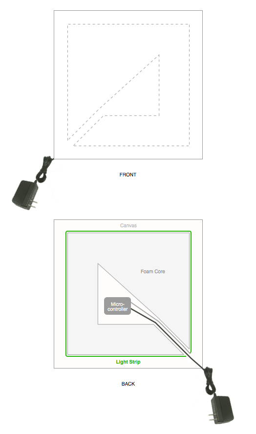
Consider where you’re going to hang this. Think about where the power cord will go. By default I have it set up so the power cord trails off from the bottom left.
If you want your power cord to lead out from a different corner: Quickly sketch which side should be top, and where it is relative to the power cord slot, from both front and back. Open up the firmware code and change the order of light zones (“TR” for top right,” “BL” for bottom left, etc.) so they match your new orientation. Here’s how they’re ordered: the first zone in the list starts with the first LED on the side of the strip where it connects to the microcontroller. So if you don’t want that side to be “left” (the default), adjust the order of zones in the code so it’s right, top or bottom.
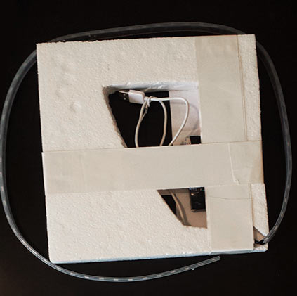
It’s time to create a little chamber for the microcontroller. If you didn’t use the JST snap connectors, you’ll first want to put the microcontroller inside, and the light strip outside. If you used the connectors, it’ll be easier to do that after taping. Either way: snugly duct tape around the foam core shape in two directions to form a sort of “+” shape (see below), but use sheets of paper to cover the sticky side where it’s not touching the foam. That way the electronics won’t stick to the inside of the tape.
Next, make the hanger. Examine the ruler (or other similar sturdy, flat, long object with holes) and find two holes in it that are far from one another. Tie one end of your picture-hanging wire to one of those holes using this technique. Now hold your ruler even near the top back edge of the foam – that’s where it will go. Figure out how much slack you’ll need: Make it tight enough that, in the middle where it will loop over the nails in your wall, it won’t rise over the edge of the canvas and be visible. But make it loose enough so the nails will be above the foam. Err a little on the side of too tight. Tie off and snip off the other end of the picture-hanging wire there.
Now duct-tape the ruler solidly to the foam. (But leave enough space in the center so you’ll have access to the microcontroller.) Wrap a loop of tape tightly around the left and right edges, and be sure to solidly wrap tape around in the up-and-down direction too so the hanger doesn’t slip.
Now it’s time to secure the light strip. Stretch it tightly all the way around the edge of the foam. You want the start of the strip to almost touch the end. Power up the microcontroller so you can see where the light zones separate – make sure the corners touch the borders between zones. Take care not to bend any point on the strip back and forth too many times – that can break the connections inside. You’ll probably have to make a few little adjustments to the foam core to get it just right – carve off a bit of styrofoam here and there if the ends are too far from one another, add a bit of tape if there’s too much slack, etc.
Make sure it’s flush with the edge of the foam or a bit towards the center – don’t let it ride out past the edges of the foam, especially not on the side where the foam will adhere to the canvas. Leave your TrainLight powered on as you go, so you keep the corners in the right places.
Once you get it just right, use the transparent packing tape to secure the light strip in place. Wrap strips tightly all the way around the foam core, but again: leave enough space open in the center so you can reach the microcontroller.
Now it’s time to attach the foam core to the canvas with spray adhesive. Remove the microcontroller if you used the JST connectors. Use blue painter’s tape to seal off the all exposed electronics, and protect them from the spray. Place the canvas upside-down on a clean flat table, then place the foam assemblage on top of it. Use a ruler to get it centered. Use a pencil to trace the edges. Remove the foam and place blue painter’s tape over the outside edges, ending at the pencil marks, so the center part will be the only part with glue. Now take the foam and canvas outside and follow the directions on the spray adhesive can to glue the foam to the canvas. After it’s dry, remove the blue painter’s tape from the canvas.
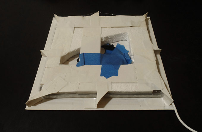
Now there’s just one last thing to do – cut and fold pieces of card-stock paper to form eight barriers between the light zones. Place them while your Trainlight’s on so you set them just right between zones. Tape them down. It will look like this:
Now hang it on the wall and you’re done!
Let me know how it works out for you.
